Site Map
Home Page
Process Engineer
Chart Digitizer
Topic Editor
Video Timer
Photo Music
PLC Simulator
Android Timer
Alien Vision
Feedback
About GTS

PLC Simulator
Product Overview
Download
This PLC simulator will allow the user to edit a page of ladder logic and watch it run. It is fairly simple and generic, rather than trying to match any particular PLC vendor. All of the ladder functions can be used as either a contact or a coil, to allow this simulator to match a variety of PLC's.
The instructions below are taken directly from the program's help file.
It consists of 4 screens:
The Control Panel is where you can edit the individual ladder items.
The Ladder Editor is where items can be added and wired to the ladder.
The PLC editor displays and modifies the input contacts and output lights.
The Data Table allows scratchpad data unrelated to IO.
These four screens interact with each other so a change on one screen will be update on the other screens.
LOAD/SAVE PROGRAM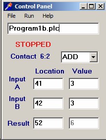
Enter the name of the program that you want to load or save in the top editline of the Control Panel.
The FILE/LOAD menu item will load the program listed on that line. There is no folder browser. There is a confirmation box, afterwhich any displayed program will be overwritten. This does not care what the file name or extension is, and will attempt to load or save any name that is on the line.
The FILE/SAVE menu item will save the program using the name listed on the editline. It will popup a confirmation first.
The FILE/ SET RUNGS menu item will allow you to change the number of rungs and colums that the ladder will use. Rungs can be set to a value between 10 and 25. Columns can be set to a value between 6 and 9; The default is 6 rungs and 10 columns. This ladder can be changed safely while a program is displayed, but coils on the right will have to be manually moved.
The RUN menu has these functions:
SHOW PROGRAM will display the three editor windows if they have been turned off. It will also clean up the PLC diagram by removing any contacts or lights that are not being used on the ladder.
RUN PROGRAM will cause the ladder to scan once per second. The ladder logic will normally execute on the fly as the ladder is edited, but timers will execute only while the program is running.
STOP PROGRAM will stop the program (and timers) from running. It does not reset the timers.
EDIT LADDER LOGIC
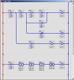
All ladder logic editors display relay contacts and coils so they appear to be a schematic. Contacts are drawn on the left and coils are at the right. Power is applied on the vertical rung at left and then flows left to right through the contacts to energise the coils.
Contacts usually represent a physical contact input to the PLC.
Coils usually represent a physical device on the output of the PLC.
Either can also be a piece of data in the internal memory, so that a coil on the ladder can drive a contact elsewhere on the ladder.
All ladder functions can go anywhere on the ladder diagram. For example, it is common for several contacts on the left to feed one coil on the right, but you can also have one contact on the left feed several coils on the same rung. This allows the layout to match PLC variations from a variety of manufacturers.
A PLC ladder logic program is far more versatile than physical relays, and can include relays, timers, and math operations.
All items on the ladder editor and the control panel appear in this format:
Item type
Input A location & value
Input B location & value
Result location & value
The Result refers to the result of the logic operation, not the power output. All items on this editor can be used as a contact (left) or coil (right). They will work exactly the same either way but some orientations make more sense than others.
These items can be used:
Normally Open and Normally Closed Contacts
Relay Coil (which can drive other contacts)
Greater Than, Less Than, Equal To Contacts
An assortment of pulse and delay timers
Math operations (do not engage contacts)
All of these functions are described in detail at the bottom of this document.
The ladder logic editor will allow you to add/remove/change any item on the ladder and direct its inputs and outputs. Contacts and coils will update the ladder logic automatically as they are edited, but the timers will run only if the program is running.
As the ladder is edited, the schematic is color coded to reflect whether power is flowing:
RED wires are passing power.
BLUE wires are not passing power.
In addition, all items show the data value of its inputs.
To add an item to the ladder, right click the location where you want it, then in the popup menu click Add Contact or Add Coil. This will place an item at that location with the name "X". The new item will have the wire input connected from its contact to the power source to its left. Its IO parameters will appear in the control panel.
The control panel lets you set these parameters:
Type: Select the type of item from this dropdown list.
Input A: The IO location that will enable this item.
Input B: The second IO location on items that have two.
Result: The IO location for the logic result if it has one.
On most items the result will be the IO location of the contact.
On coils it is the IO location of the coil.
On math functions it is the data location of the result.
The left three edits are the IO location, the right three are the actual value stored at that location. Only those locations and values that apply to that item will be enabled.
Right click on an item and the popup menu will have these functions:
ADD CONTACT was described above.
CONNECT INPUT 1, will reconnect the wire on the left to a different source. The source must be to the left of the item. Just click the item that you want to connect to.
CONNECT NEXT INPUT, will connect up to 9 wires on the left to a different source.
REMOVE LAST, will remove the most recent input wire from an item.
TOGGLE INPUT A, will toggle Input A between 0 and 1, on the PLC.
TOGGLE INPUT B, will toggle Input B between 0 and 1.
ADD RUNG will insert a blank rung at that location.
REMOVE RUNG will remove a rung from that location.
The ladder logic updates automatically as it is edited, but the timers will require the program to run. To do this, click RUN PROGRAM on the main menu. This will cause the program to scan once per second and increment the timer's counter.
For all timers:
Input A is the setpoint in seconds.
Input B is the time value as it counts.
See the Timer section at bottom for details on the behavior of the different timers.
The ladder will evaluate in this order:
Left column from top to bottom,
then column 2 from top to bottom,
then columns 3, 4, 5, 6.
It will scan the whole ladder twice so that coils in column 6 can be reapplied to the contacts on the left.
Note that the wiring will only evaluate from left to right, it will not backfeed from right to left.
EDIT PLC IO
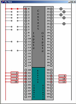
The PLC diagram represents physical inputs and outputs of the PLC. The Data Table represents scratch pad memory that can be used when an IO is not needed.
Note, in its current state, this simulator only works with integer data.
The IO and Data are allowed in these specific locations:
PLC:
Contact Inputs = addresses 0-19 = 0 or 1
Contact Outputs = addresses 20-39 = 0 or 1
Analog Inputs = addresses 40-49 = integers
Analog Outputs = addresses 50-59 = integers
Data:
General Data = addresses 60-99 = integers
Note that this data is generally interchangable. If a contact or coil input is reading an analog value, positive values will enable the contact, zero and negative will disable. All values are limited to integers.
The input to a ladder item can come from the output of another item. But, if you manually change an output on the control panel it will change on the PLC, but will be overwritten on the next PLC scan. This does not prevent multiple (conflicting) coils from driving the same output location, which could cause eratic operation.
The PLC screen shows a diagram of the PLC with its inputs on the left and outputs on the right. Any contact input or coil output that is used on the ladder diagram will automatically show a contact input or lamp output on the PLC diagram. Analog inputs are at the bottom left and analog outputs at the bottom right. These will also appear when they are used on the ladder diagram.
You can not add or remove these inputs or outputs directly (that is done on the ladder editor) but you can change their values:
Click a contact input to toggle from open to close or vice versa.
Click an analog input to edit the value.
Outputs can not be edited but will be updated when the ladder editor is changed or while the program is running.
As these values are edited, the values are reflected back to the ladder editor. As the ladder is edited, the new values will be reflected here. If a ladder item is no longer using an IO point, you can remove that point from the diagram by clicking Run/ShowPLC from the control panel. That will refresh all IO points on the PLC diagram.
The Data Table window shows the scratchpad data table. This list has data locations 60 to 99 and can hold integers without regard for inputs and outputs, or digital and analog. They can all be edited as needed.
RUN LADDER PROGRAM
As contacts and coils are added to the ladder editor, the power will be flowed through the contacts and coils automatically. But the timers will not count or toggle unless the program is running.
To run the timers, use the RUN PROGRAM item on the control panel menu.
Run Program, will run the program and allow the timers to function.
Stop Program, will stop the program (and timers) but normal contacts will continue to apply correct logic while they are edited.
LADDER FUNCTIONS
These are the characteristics of the specific ladder functions.
All functions can go anywhere on the ladder diagram.
It is important to visualize how all items work:
Power is connected from the wire at left to the contact input.
The contact is energised but the logic inputs.
Power is output from the contact only if power is input and the logic is true.
The items below follow this pattern:
Power Input: Connects power to the contact.
Power Output: Power output controlled by item logic.
Input A & B: drives the logic, from PLC input or data table.
Result: result of logic, saved to PLC output or data table.
On timers & coils, Result is the power output.
On math functions, Result is the result of operation.
Not used on NOC, NCC, GTH, LTH, EQU.
All PLC in/out or data table values can be shared by multiple items. For example: the incrementing counter of a timer can be used as an input to a math operation.
* Contacts:
Power Output: controlled by logic.
Input A: controlls the logic (PLC input or data table).
Input B: not used.
Result: not used.
NOC: Normally Open Contact
Power Output if: power in and Input A > 0.
NCC: Normally Closed Contact
Power Output if: power in and Input A = 0.
* Coil:
Power Input: Supplies power to the coil.
If power is input, the coil is on.
Power Output: power input is reflected to the output.
This allows coils to be daisy chained from one contact.
Input A & B: not used.
Result: Power Output (PLC input or data table).
This allows other contacts to be driven by this coil.
COL: Coil
* Logic:
Power Output: controlled by logic.
Input A & B: controlls the logic (PLC input or data table).
Result: not used.
GTH: Greater Than
Power Output if: power in and Input A > B.
LTH: Less Than
Power Output if: power in and Input A < B.
EQU: Equal To
Power Output if: power in and Input A = B.
* Timers:
Timers only work if the program is running.
Outputs will turn off if program is not running.
The timer will reset each time contact input is enabled.
Power Input: Enables the contact and timer.
Power Output: Controlled by logic.
Input A: Timer Setpoint (PLC input or data table).
Input B: Timer Counter (PLC input or data table).
Result: Power Output (PLC output or data table).
ONP: On Pulse
Power Output goes ON when input goes ON.
Then Counter will increment with each clock tick.
Then power output goes OFF when Counter = Setpoint.
OND: On Delay
Power Output stays OFF when input goes ON.
Then increment Counter with each clock tick.
Then power output goes ON when Counter = Setpoint.
TIM: Cycle Timer
Timer is enabled and Power Output turns on when input goes ON.
Then Counter will increment with each clock tick.
Then power output goes OFF when Counter = Setpoint.
Then Counter will reset and increment with each clock tick.
Then power output goes ON when Counter = Setpoint.
On/Off cycle will repeat as long as the power input is enabled.
CNT: Counter
Power Output is OFF if Counter is less than Setpoint.
Then Counter will increment each time power input goes 0 to 1.
Then power output goes ON when Counter = Setpoint.
The counter will have to be reset manually.
A Counter will count even if the program is not running.
* Math:
Power Input: Enables the function.
The math operation only takes place when the power is enabled.
If input is disabled then the output retains last known value.
Power Output: power input is reflected to the output.
This allows math functions to be daisychained from one contact.
Note the scan order when daisychaining: top-down then left-right.
Input A & B: Numeric input. (PLC output or data table).
Result: Numeric result of the function. (PLC output or data table).
The Result will usually become Input A for the next function.
ADD: Result = Input A plus Input B
SUB: Result = Input A minus Input B
MUL: Result = Input A times Input B
DIV: Result = Input A divide by Input B